
The role of circuit board grounding and common grounding methods
2024-01-26
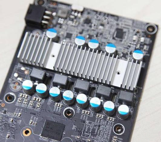
Circuit boards are one of the most basic components of modern electronic devices. The various components on the circuit board are connected together by metal wires to form complex circuits. In these circuits, grounding is crucial. This article will introduce the basics of grounding in circuit boards to help readers better understand the design and manufacture of circuit boards.
1. Definition and function of grounding
"Earth" is defined in electronics as: an equipotential point or plane that serves as a reference for a circuit or system. The GND on the circuit diagram and board stands for ground or neutral. The more common "ground" in switching power supply mainly includes AC ground, DC ground, analog ground, digital ground, signal ground, etc.

Grounding refers to the connection of a circuit with the earth to form a reference point for the circuit and a loop for the current. The main function of grounding is to ensure the safety and stability of the circuit. In electrical circuits, grounding can play the following roles:
(1) Protect the personnel and equipment in the circuit
By grounding, the current in the circuit can flow back to the ground, protecting people and equipment from hazards such as electric shock.
(2) Suppression of electromagnetic interference
In circuit boards, many signals and power lines need to be grounded. These grounding points can eliminate electromagnetic interference between the signal and the power line, improving the reliability and stability of the circuit.
(3) Stabilize voltage and current
In circuit boards, grounding also stabilizes voltage and current, keeping them stable within a certain range.
2. the common grounding method in the circuit board
In circuit boards, there are three common types of grounding: single-point ground, multi-point ground, hybrid ground, and virtual ground.
(1) Single-point grounding
A single point of ground refers to connecting all signals and power lines to the same ground point. This is the simplest and easiest to implement. However, if the circuit board is large or the current is large, a single point of ground may cause the ground resistance to be too large, which will affect the stability and reliability of the circuit. As shown in the figure below:

(2) Multi-point grounding
Multi-point grounding refers to connecting the signal and power lines to different grounding points, respectively. This method can effectively reduce the ground resistance, reduce electromagnetic interference and signal reflection and other problems. However, multi-point grounding requires precise control in board design and manufacturing to ensure that the potential is the same at each ground point. As shown in the figure below:

(3) Mixed grounding
Hybrid grounding is a grounding method that combines single-point grounding and multi-point grounding, which is generally multi-point grounding through some inductors or capacitors on the basis of single-point grounding. Because inductors and capacitors have different impedances at different frequencies, they constitute different grounding structures. Hybrid grounding is mostly suitable for circuits that operate at mixed frequencies.
(4) Void land
Imaginary ground refers to connecting a ground point to another signal line instead of an actual ground wire. Virtual ground eliminates ground loops in board designs and reduces electromagnetic interference. However, virtual ground requires sophisticated control and testing to ensure that it works properly.
Solutions to common defects in PCB boards
What is PCB board impedance control?



SEND MESSAGE