
PCB has the difference between leaded solder and lead-free solder
2026-02-05
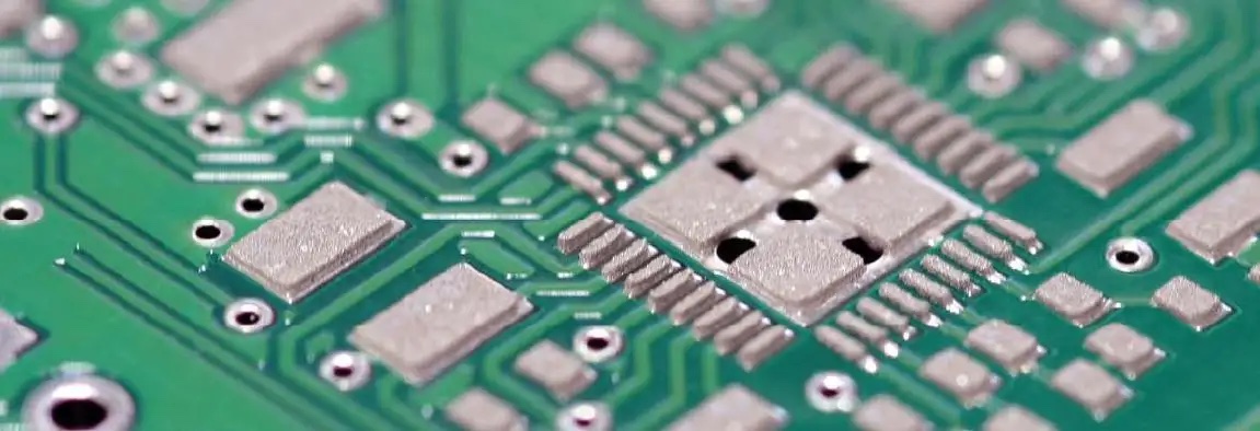
There is an essential difference between lead-tin (usually tin-lead alloys, such as Sn63/Pb37) and lead-free tin (the main component is tin, and silver, copper, bismuth, etc., such as SAC305) used in PCB soldering, and its choice directly affects the production process, product performance and reliability. The core differences are as follows:
1. Material composition and environmental protection
Lead and tin: the main components are tin and lead (lead content is about 37%). Lead is a toxic heavy metal that is seriously harmful to human health and the ecological environment. With the implementation of global environmental regulations such as the EU RoHS Directive, the vast majority of consumer electronics have made it mandatory to ban lead-containing solder.
Lead-free tin: mainly tin, with silver (Ag), copper (Cu) and other metals added (such as common SAC305: Sn96.5/Ag3.0/Cu0.5). Its formulation is designed to replace lead, meeting environmental requirements but often at a higher cost.
Lead-free tin: mainly tin, with silver (Ag), copper (Cu) and other metals added (such as common SAC305: Sn96.5/Ag3.0/Cu0.5). Its formulation is designed to replace lead, meeting environmental requirements but often at a higher cost.
2. Comparison of welding process performance
Melting point temperature: The eutectic melting point of lead-tin is about 183°C, while the melting point of lead-free tin (such as SAC305) is around 217-220°C. Higher melting points require lead-free processes to use more high-temperature PCB substrates and components, and adjust the temperature profile of reflow/wave soldering (typically 10-30°C higher peak temperature), which is challenging for process control, energy consumption, and heat-sensitive components.
Wettability and welding effect: The wettability (fluidity) of lead and tin is better, and it is easier to form smooth and bright solder joints during welding, and the process window is wide, making it easier to master the operation. Lead-free tin has relatively poor wettability, and the surface of the solder joints is often rougher and darker gray, and it is easy to produce defects such as "virtual soldering" and "monument", and the requirements for solder paste printing and nitrogen protection are stricter.
3. Differences in solder joint mechanics and reliability
Mechanical strength: Lead-free solder joints are harder and more brittle, and may be better than leaded solder joints in creep and fatigue resistance, but generally weaker in impact resistance (e.g., dropping, bending) and have a higher risk of solder joint cracking.
Long-term reliability: Leaded solder joints have good toughness and are not prone to fatigue fracture due to coefficient of thermal expansion (CTE) mismatch during temperature cycling. The reliability of lead-free solder joints is highly dependent on alloy formulation and process optimization, and may require special validation in some harsh environments (e.g., high and low temperature cycling, vibration).
4. Economy and application fields
Cost: Lead-free tin has higher material costs due to the presence of precious metals such as silver; At the same time, the increase in energy consumption, equipment transformation, yield fluctuations and testing requirements also pushed up the comprehensive production cost.
Applications: Lead-tin is still used in some high-reliability, military, aerospace, or specific medical device applications where long-term reliability is extremely demanding and not subject to environmental regulations. Lead-free tin has become a mandatory or standard choice in mainstream fields such as consumer electronics, automotive electronics, and industrial equipment.
The core differences between leaded tin and lead-free tin are environmental protection, process temperature and solder joint characteristics. Lead-free is an irreversible environmental trend in electronics manufacturing, but it is not a simple replacement, but a systematic upgrade involving material, process, equipment and reliability verification. Engineers must balance design, manufacturing, and cost to make the right choice based on product application and regulatory requirements.
How Does the Quality of Conformal Coating Affect PCBA Circuit Boards?
What is the shelf life of a PCB? How to extend the life of your PCB



SEND MESSAGE