
Through-Hole vs SMT Assembly: Which One Fits Your Project?
2026-04-22
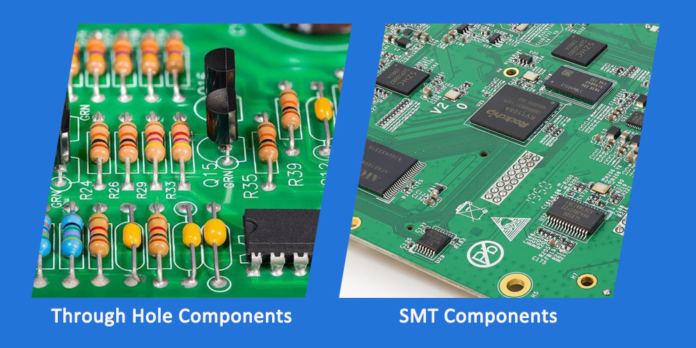
When designing a PCBA, one of the first decisions is component mounting method. Through-Hole and Surface Mount (SMT) each have distinct advantages.
At STG Electronic Co., Ltd, we’ve assembled both types for global clients since 2002. Here’s a quick comparison.
Key Differences
Feature Through-Hole SMT
Mounting method Leads inserted into drilled holes Components placed on pad surface
Soldering Wave soldering or manual Reflow soldering
Mechanical strength Very strong (ideal for connectors) Moderate
Component size Larger Smaller, lighter
Rework ease Easy with basic tools Requires specialized equipment
Cost Higher per joint Lower per joint
Density Low High (more components per board)

When to Use Through-Hole
- Connectors – USB, power jacks, headers
- Large components – Transformers, relays, electrolytic capacitors
- High-stress applications – Automotive, industrial equipment
- Prototyping – Easy to swap parts
When to Use SMT
- High-volume production – Faster, cheaper per board
- Space-constrained designs – Smartphones, wearables, IoT devices
- High-speed circuits – Shorter signal paths, better performance
- Double-sided assembly – Maximize board utilization
The Hybrid Approach (Most Common)
Most modern PCBs use SMT for the majority of components and Through-Hole only for connectors or mechanically stressed parts.
STG Electronic supports both technologies and handles hybrid designs seamlessly.

Why Choose STG Electronic?
- 24 years of PCBA experience
- In-house SMT + wave soldering lines
- ISO9001:2015 certified
- X-ray + AOI for 100% BGA inspection
Need Help Choosing the Right Assembly Method?
Send us your Gerber files and BOM. We’ll respond with a free assembly recommendation and a quote—within 24 hours.
No obligation. Just practical advice.
What is the difference between ENIG and electroplated gold finish on PCBs?
5-Day PCBA Prototyping: How STG Electronic Accelerates Your Time-to-Market



SEND MESSAGE