
The importance and analysis of PCB circuit board heat dissipation design
2023-11-25
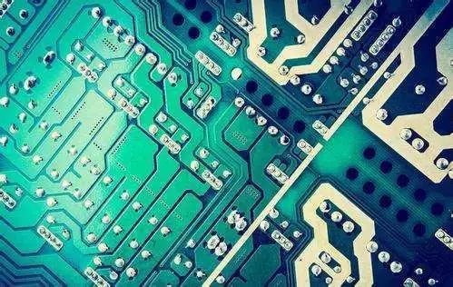
For PCB circuit board heat dissipation is a very important link, then PCB circuit board heat dissipation skills are what, let's discuss the next.
First, the importance of thermal design
The electrical energy consumed by electronic devices during work, such as RF amplifiers, FPGA chips, and power supply products, in addition to useful work, most of it is converted into heat dissipation. The heat generated by electronic equipment makes the internal temperature rise rapidly, if the heat is not dissipated in time, the equipment will continue to heat up, the device will fail due to overheating, and the reliability of the electronic equipment will decline. SMT increases the installation density of electronic equipment, reduces the effective heat dissipation area, and seriously affects the reliability of equipment temperature rise. Therefore, the research of thermal design is very important.
Second, printed circuit board temperature rise factor analysis
The direct cause of PCB temperature rise is due to the existence of circuit power consumption devices, electronic devices have varying degrees of power consumption, heating intensity changes with the size of power consumption.
Two phenomena of temperature rise in printed boards:
(1) local or large area temperature rise;
(2) short-time temperature rise or long-term temperature rise. When analyzing PCB thermal power consumption, it is generally analyzed from the following aspects.
Two phenomena of temperature rise in printed boards:
(1) local or large area temperature rise;
(2) short-time temperature rise or long-term temperature rise. When analyzing PCB thermal power consumption, it is generally analyzed from the following aspects.
2.1 Electrical Power consumption
(1) Analysis of power consumption per unit area;
(2) Analyze the distribution of power consumption on the PCB board.
2.2 Structure of the printed board
(1) the size of the printed board;
(2) Printed board materials.
2.3 Installation method of the printed board
(1) Installation method (such as vertical installation, horizontal installation);
(2) Sealing condition and distance from the housing.
2.4 Thermal radiation
(1) the radiation coefficient of the printed board surface;
(2) The temperature difference between the printed board and the adjacent surface and their absolute temperature
2.5 Heat Conduction
(1) Install heat sink;
(2) Conduction of other mounting structural parts.
2.6 Thermal Convection
(1) natural convection;
(2) Forced cooling convection.
The analysis of the above factors from the PCB is an effective way to solve the temperature rise of printed boards, often in a product and system these factors are interrelated and dependent, most factors should be analyzed according to the actual situation, only for a specific actual situation in order to more correctly calculate or estimate the temperature rise and power consumption and other parameters.
Third, some methods of PCB thermal design
1. Heat dissipation through the PCB board itself
At present, the widely used PCB board is copper-coated/epoxy glass cloth substrate or phenolic resin glass cloth substrate, and there is a small amount of paper-based copper-coated sheet. Although these substrates have excellent electrical properties and processing properties, they have poor heat dissipation, and as a heat dissipation pathway for high-heating components, they can hardly be expected to conduct heat by the PCB itself, but to dissipate heat from the surface of the component to the surrounding air. However, as electronic products have entered the era of component miniaturization, high-density installation, and high-heat assembly, it is not enough to rely only on the surface of a very small surface area to dissipate heat. At the same time, due to the large use of surface mounted components such as QFP and BGA, the heat generated by the components is transmitted to the PCB board in large quantities, therefore, the best way to solve the heat dissipation is to improve the heat dissipation capacity of the PCB itself in direct contact with the heating element, which is transmitted or distributed through the PCB board.
2. High heating device with heat sink, heat conduction plate
When the PCB has a small number of devices with large heat (less than 3), the heat sink or heat conduction tube can be added to the heating device, and when the temperature can not be lowered, the radiator with a fan can be used to enhance the heat dissipation effect. When the amount of heating devices is large (more than 3), a large heat shield (plate) can be used, which is a special radiator customized according to the position and height of the heating device on the PCB board, or a large flat radiator to cut out the height of different components. The heat shield is fastened on the component surface as a whole, and the heat is dissipated by contact with each component. However, due to the poor consistency of the components during installation and welding, the heat dissipation effect is not good. Usually add a soft thermal phase change thermal pad on the surface of the component to improve the heat dissipation effect.
When the PCB has a small number of devices with large heat (less than 3), the heat sink or heat conduction tube can be added to the heating device, and when the temperature can not be lowered, the radiator with a fan can be used to enhance the heat dissipation effect. When the amount of heating devices is large (more than 3), a large heat shield (plate) can be used, which is a special radiator customized according to the position and height of the heating device on the PCB board, or a large flat radiator to cut out the height of different components. The heat shield is fastened on the component surface as a whole, and the heat is dissipated by contact with each component. However, due to the poor consistency of the components during installation and welding, the heat dissipation effect is not good. Usually add a soft thermal phase change thermal pad on the surface of the component to improve the heat dissipation effect.
3. For devices that use free convection air cooling, it is best to arrange integrated circuits (or other devices) by longitudinal length or by transverse length.
4. Adopt reasonable cable design to realize heat dissipation
Since the resin in the plate has poor thermal conductivity, and the copper foil line and hole are good conductors of heat, increasing the copper foil residual rate and increasing the heat conduction hole are the main means of heat dissipation.
Since the resin in the plate has poor thermal conductivity, and the copper foil line and hole are good conductors of heat, increasing the copper foil residual rate and increasing the heat conduction hole are the main means of heat dissipation.
To evaluate the heat dissipation capacity of PCB, it is necessary to calculate the equivalent thermal conductivity (9 eq) of the PCB insulating substrate composed of various materials with different thermal conductivity.
5. The devices on the same printed board should be arranged as far as possible according to the size of their heat and the degree of heat dissipation, and the devices with small heat or poor heat resistance (such as small signal transistors, small-scale integrated circuits, electrolytic capacitors, etc.) are placed at the upper stream of the cooling air flow (entrance). Devices with large heat generation or good heat resistance (such as power transistors, large-scale integrated circuits, etc.) are placed at the downstream of the cooling stream.
6. In the horizontal direction, the high-power device is arranged as close as possible to the edge of the printed board in order to shorten the heat transfer path; In the vertical direction, the high-power devices are arranged as close as possible to the printed board, in order to reduce the impact of these devices on the temperature of other devices when they work.
7. The heat dissipation of the printed board in the equipment mainly depends on the air flow, so the air flow path should be studied in the design, and the device or printed circuit board should be reasonably configured. When the air flows, it always tends to flow where the resistance is low, so when configuring the device on the printed circuit board, it is necessary to avoid leaving a large airspace in a certain area. The configuration of multiple printed circuit boards in the whole machine should also pay attention to the same problem.
8. The device that is more sensitive to temperature is best placed in the lowest temperature area (such as the bottom of the device), do not put it above the heating device, and multiple devices are best staggered on the horizontal plane.
9. Arrange the device with the highest power consumption and the greatest heat dissipation near the best location for heat dissipation. Do not place devices with high heat in the corners and edges of the printed board, unless a cooling device is arranged near it. When designing the power resistance, choose a larger device as much as possible, and adjust the layout of the printed board so that it has enough space for heat dissipation.
10. Rf power amplifier or LED PCB adopts metal base substrate.
11. Avoid the concentration of hot spots on the PCB, distribute the power evenly on the PCB board as much as possible, and maintain the uniform and consistent temperature performance of the PCB surface. It is often difficult to achieve strict uniform distribution in the design process, but it is necessary to avoid areas with too high power density to avoid hot spots that affect the normal operation of the entire circuit. If there are conditions, it is necessary to carry out thermal performance analysis of printed circuits, such as the thermal performance index analysis software module added to some professional PCB design software, which can help designers optimize circuit design.
Iv. Summary
3.1 Material Selection
(1) The temperature rise caused by the wire of the printed board through the current plus the specified ambient temperature should not exceed 125 ° C (commonly used typical value. May vary depending on the plate chosen). Since the components installed on the printed board also emit a part of the heat, affecting the working temperature, the selection of materials and printed board design should take these factors into account, the hot spot temperature should not exceed 125 ° C. Choose a thicker copper-covered foil if possible.
(2) In special cases, aluminum base, ceramic base and other panels with small thermal resistance can be selected.
(3) The use of multi-layer board structure is conducive to PCB thermal design.
3.2 Ensure that the heat dissipation channel is smooth
(1) Make full use of component layout, copper skin, window opening and heat dissipation hole and other technologies to establish a reasonable and effective low thermal resistance channel to ensure that the heat is successfully exported to the PCB.
(2) The design of some heat dissipation through holes and blind holes can effectively improve the heat dissipation area and reduce thermal resistance, and improve the power density of the circuit board. For example, a through hole is set up on the pad of the LCCC device. In the circuit production process, the solder will fill it, so that the heat conduction capacity is improved, and the heat generated during the circuit work can be quickly transmitted to the metal heat dissipation layer or the copper moor set on the back through the hole or blind hole. In some specific cases, a circuit board with a cooling layer is specially designed and used, and the cooling material is generally copper/molybdenum and other materials, such as the printed board used on some module power supplies.
(3) The use of thermal conductive materials In order to reduce the thermal resistance of the heat conduction process, the use of thermal conductive materials on the contact surface of the high-power device and the substrate to improve the heat conduction efficiency.
(4) The process method is easy to cause local high temperature in some areas with double-sided devices, in order to improve the heat dissipation conditions, a small amount of fine copper can be added to the solder paste, and then the solder joint under the device will have a certain height after flow welding. The gap between the device and the printed board is increased, and the convection heat dissipation is increased.
3.3 Layout Requirements of Components
(1) Software thermal analysis of PCB and design control of the maximum internal temperature rise;
(2) can consider the high heat, large radiation components specially designed to install on a printed board;
(3) The heat capacity of the plate surface is evenly distributed, pay attention not to centralized distribution of high-power devices, if it is unavoidable, it is necessary to put the short components in the upstream of the air flow, and ensure that sufficient cooling air flow through the heat consumption concentration area;
(4) Make the heat transfer path as short as possible;
(5) Make the heat transfer cross section as large as possible;
(6) Component layout should take into account the impact of thermal radiation on surrounding parts. Heat-sensitive parts and components (including semiconductor devices) should be kept away from heat sources or isolated;
(7) (liquid medium) capacitor is best away from heat source;
(8) Pay attention to the direction of forced ventilation and natural ventilation;
(9) The attached sub-board, the device air duct and the ventilation direction are consistent;
(10) as far as possible to make the intake and exhaust have sufficient distance;
(11) The heating device should be placed above the product as far as possible, and should be in the gas flow channel when conditions permit;
(12) Components with large heat or current should not be placed in the corners and edges of the printed board, as long as possible should be installed on the radiator, and away from other devices, and ensure that the heat dissipation channel is smooth;
(13) (small signal amplifier peripheral devices) try to use small temperature bleach devices;
(14) Use metal chassis or chassis heat dissipation as much as possible.
3.4 Requirements for Cabling
(1) plate selection (reasonable design of printed board structure);
(2) Wiring rules;
(3) Plan the minimum channel width according to the device current density; Pay special attention to the channel wiring at the junction;
(4) The large current lines are as superficial as possible; In the case that the requirements cannot be met, the bus can be considered;
(5) To minimize the thermal resistance of the contact surface. Therefore, the heat conduction area should be increased; The contact surface should be smooth and smooth, and can be coated with thermal grease if necessary.
(5) To minimize the thermal resistance of the contact surface. Therefore, the heat conduction area should be increased; The contact surface should be smooth and smooth, and can be coated with thermal grease if necessary.
(6) Thermal stress points consider stress balance measures and add bold lines;
(7) The heat dissipation copper sheet should use the heat dissipation stress opening method, and the heat dissipation resistance welding should be used to open the window properly;
(8) Large surface area copper foil may be used;
(9) The ground mounting hole on the printed board is equipped with a large solder pad to make full use of the mounting bolts and copper foil on the surface of the printed board for heat dissipation;
(8) Large surface area copper foil may be used;
(9) The ground mounting hole on the printed board is equipped with a large solder pad to make full use of the mounting bolts and copper foil on the surface of the printed board for heat dissipation;
(10) Place as many metallized holes as possible, and the aperture and disk surface are as large as possible, relying on the holes to help heat dissipation;
(11) Supplementary means of device heat dissipation;
(12) In the case that a large area of copper foil on the surface can be guaranteed, additional heat sinks may not be used for economic considerations;
(13) According to the device power consumption, ambient temperature and the maximum allowable junction temperature to calculate the appropriate surface cooling copper foil area (guarantee principle tj≤ (0.5 ~ 0.8) tjmax).
(13) According to the device power consumption, ambient temperature and the maximum allowable junction temperature to calculate the appropriate surface cooling copper foil area (guarantee principle tj≤ (0.5 ~ 0.8) tjmax).
PCBA storage conditions and requirements at different stages
PCB assembly inspection and testing options Guide



SEND MESSAGE