
PCBA Thermal Management: 4 Design Tips to Prevent Overheating
2026-05-13
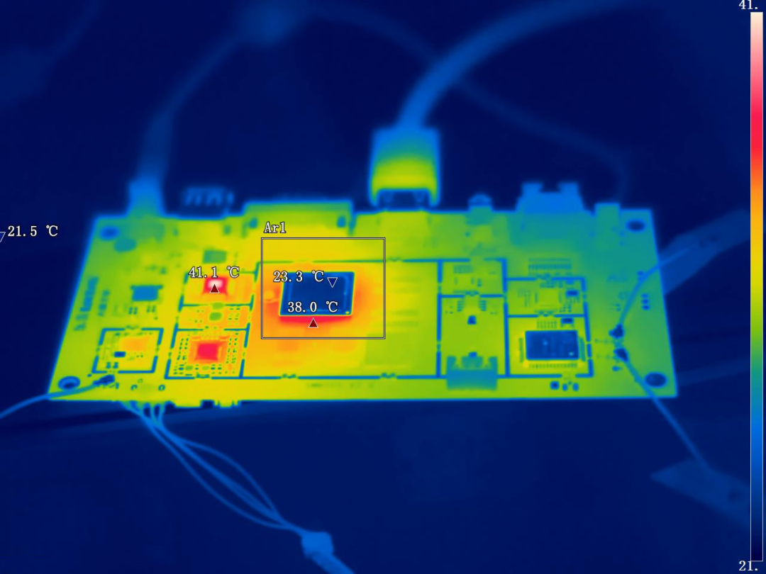
Heat is the silent killer of electronics. Every 10°C rise above rated temperature cuts component life in half.
At STG Electronic Co., Ltd, we've helped global clients design and assemble thermally reliable boards since 2002. Here are four practical tips.
1. Use Thermal Vias Under Hot Components
Problem: Heat gets trapped under power ICs, LEDs, and voltage regulators.
Solution: Add small plated holes (thermal vias) directly under the component pad. They conduct heat to inner copper layers or the bottom side.

STG tip: Use multiple small vias (0.3–0.5mm) rather than one large via. More surface area = better heat transfer.
2. Increase Copper Weight on Power Layers
Problem: Thin copper traces act like a bottleneck for heat flow.
Solution: Use 2oz or 3oz copper instead of standard 1oz on power and ground layers.
Copper Weight Current Capacity Heat Dissipation
1 oz Baseline Baseline
2 oz +100% +40%
3 oz +150% +60%
1 oz Baseline Baseline
2 oz +100% +40%
3 oz +150% +60%

STG tip: For high-power designs, specify 2oz minimum on outer layers and 1oz on inner layers.
3. Add Active Cooling Early
Problem: Boards pass lab testing but fail in the field under real loads.
Solution: Don't rely only on passive cooling (copper, vias). Plan for fans, heat sinks, or enclosure vents from the start.
STG tip: Mock up your worst-case power draw and measure temperatures on a prototype. Add cooling margin—never design at the limit.
4. Select the Right PCB Material
Problem: Standard FR-4 has poor thermal conductivity (0.3–0.4 W/m·K).
Solution: For high-heat applications (LED lighting, motor drives, power supplies), consider:
Material Thermal Conductivity Best For
FR-4 (standard) 0.3–0.4 W/m·K General purpose
FR-4 (high Tg) 0.5–0.7 W/m·K Elevated ambient temps
Aluminum core (IMS) 1–3 W/m·K High-power LEDs
Ceramic 20–30 W/m·K Extreme power density
FR-4 (standard) 0.3–0.4 W/m·K General purpose
FR-4 (high Tg) 0.5–0.7 W/m·K Elevated ambient temps
Aluminum core (IMS) 1–3 W/m·K High-power LEDs
Ceramic 20–30 W/m·K Extreme power density

STG tip: For most industrial and automotive designs, high-Tg FR-4 with thermal vias is sufficient. Reserve IMS or ceramic for extreme cases.
What STG Does Differently
DFM review – We flag thermal issues before production
Material sourcing – We stock high-Tg FR-4 and IMS materials
Assembly expertise – Proper solder paste and reflow for thermal pads
Testing support – Thermal imaging available for prototypes
Why Thermal Management Matters
Overheating Consequence Real Cost
Component derating Reduced performance
Premature failure Warranty returns
Field safety issues Liability, recalls
Customer complaints Lost reputation
Component derating Reduced performance
Premature failure Warranty returns
Field safety issues Liability, recalls
Customer complaints Lost reputation
One overlooked thermal issue can cost 10x your PCBA price in downstream damage.
Ready to Build Boards That Run Cool?
Send us your Gerber files and BOM. We'll review your thermal design and return a free DFM report with thermal recommendations—within 24 hours.
PCBA Prototype: 5 Questions to Ask Before Placing Your Order
Genuine vs Counterfeit Components: 3 Ways to Spot Fake Chips
Related Article



SEND MESSAGE